
Results
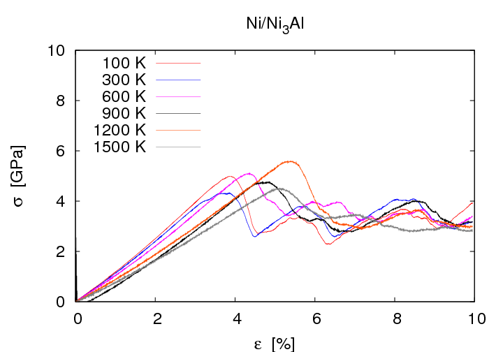
Molecular dynamics simulations were used to investigate the brittle/ductile model systems Ni/Ni3Al and Ni/NiAl. Simulated tensile tests were performed which revealed the stress strain curves in dependence on interface orientations, misfit disloctions and temperature.
Ni/Ni3 showed ductile material failure. Even at high strains no cracking was observed. Instead intrinsic stacking faults surrounded by Shockley Partials were observed at high strains. These defects which are typical for fcc crystals are generated homogenously in single crystals of Ni3Al and Ni/Ni3Al awithout misfit dislocations. On the contrary in the system Ni/Ni3Al with misfit dislocations the defects are nucleated at the misfit dislocations. At medium strain they spread exclusively into the more ductile Ni. Further increase of the strain leads to defect propagation in Ni3Al as well. The tensile strength is significantly decreased in the system with misfit dislocations. It is about 5 GPa whereas the value for the system without misfit dislocatios is about 13 GPa.
|
|
|

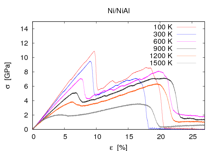
Ni/NiAl stress strain curves show a strong dependence on the orientation of the interface. I comparison to the (001) oriented interface the tensile strength of the (110) oriented interface is decreased by 4 GPa whereas the tensile strength of the (111) oriented interface is decreased by 2 GPa. Further increase of strains leads to differences regarding material failure: Cracking at the interface was observed at (001) oriented interfaces whereas (011) or (111) oriented interfaces show no fracture but increase of the defect density in the ductile material.
|
|
|

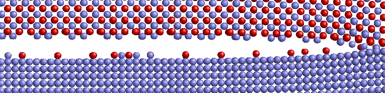
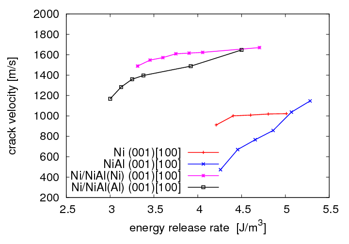
Crack propagation regarding surfcace morphology and crack velocities in the (001) oriented interface was investigated by inserting an displacement field into the structure andsimulating with fixed displacement boundary conditions. For comparison reasons the simulations were performed with Ni and NiAl single crystals as well. It was observed that the morphology of the crack surface depends on the atom types in the interface layers. Cracks in Ni terminated Ni/NiAl propagate smoothly in the interface plane whereas cracks in Al terminated Ni/NiAl lead to fragmentation of both interfacial layers. Ni atoms adhere on the Al terminated NiAl substructure and Al atoms adhere on the Ni substructure. Compared to the results observed for Ni and NiAl single crystals it was found that cracks in the interface propagate at a wider range of energy release rates. Not until more than 2,0 G0 defects in Ni are generated instead of crack propagation in the interface. The crack velocities of cracks in the interface propagating in [100] or [110] directions are clearly higher than those in the single crystals. Crack velocities in the interface are about 1200-2000 m/s which is slightly below the Rayleigh wave velocities of Ni and NiAl.
|
|
|
In the second funding period interaction potentials for molecular dynamics simulations of α-Al2O3 and Al(111)/Al2O3(0001) interfaces were developed and tested together with project B.1. Lattice constants, cohesive energy and surface energies determined with these new potentials are very close to literature values. Regarding stresses of strained configurations as well as morphology of relaxed surfaces the new potentials lead to more realistic results than previous potentials for Al2O3. Work of separation values of Al(111)/Al2O3(0001) interfaces obtained with the new potentials are close to ab initio data.
|
|

The newly developed potentials were used in molecular dynamics simulations of crack propagation in α-Al2O3. Im order to investigate in which crystallographic planes crack propagation occurs initial cracks were inserted in different orientations of the crystal. It was found that there is no crack propagation in the most densely packed {0001} planes. Instead, initial cracks from these planes propagate in a {10̅12} cleavage plane. A crack inserted in a {̅2110} plane propagates in this plane whereas initial cracks in {10̅10} planes propagate partly in this plane and partly in a {10̅12} cleavage plane. Obtained results agree well with results of experiments. In cooperation with project B.1 and D.3 the results of crack propagation simulations were visualized.
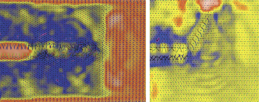
Results for (̅2110)[0001] and (0001)[0̅110] orientations are shown in Fig.8. Only oxygen atoms are shown, namely by arrows with lengths corresponding to the dipole moments of the atoms. Colours of the arrows correspond to the orientations of the dipole moments. It is visualized by the background colour to which extent the dipole moments of the corresponding region are aligned. As can be seen from Fig.8 the dipole moments are aligned in the strained region in front of the crack tip. On the other hand no aligned dipole moments were found in simulations of homogenously strained Al2O3. The alignment observed in the crack propagation simulations is caused by the strain gradient. In the following, this effect which is known as flexoelectricity was studied in detail by project B.1 In order to support these investigations molecular dynamics simulations of crack propagation in magnesium oxide were performed by project B.2.
|
|
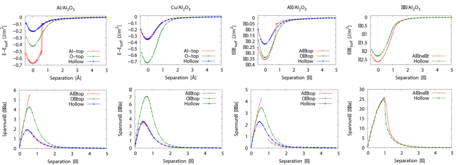
Furthermore, stress separation relationships which can be used in finite elements calculations within the cohesive zone model were determined using ab initio calculations. Separations were introduced manually into the structures and a relaxation of the atoms close to the interface was performed. From the potential energies of the relaxed structures (E) and the separations (s) the stress separation relationships are calculted according to σz= 1/A Δ E/Δ s. Results for the technological relevant interface systems metal(111)/Al2O3(0001) (metal = Al, Cu, Ag, Nb) separated orthogonal to the interface are shown in Fig.9. Maximum stresses for the fcc metals are found to be in the range from two to eight GPa wheras the maximum stress is 27 GPa in case of Nb. The analysis of charge densitity distributions and calculations of the charge transfer at the interface revealed that an ionic contribution from Nb-O bonds strengthens the bonding at the interface. Additionally, in contrary to the other metals the d-band of Nb is occupied partially which also contributes to strengthening of bonds at the interface.
|
|
Since lattice distortions due to defects or mechanical load are frequent in materials used in applications, the influence of expansion or compression in the interface plane on the work of separation and the maximum stress was investigated. It was found that expansion leads to a decrease of work of separation and maximum stress whereas compression leads to an increase of these values. This effect is significantly more pronounced in the case of metals which exhibit a non planar interface layer after relaxation.